Warning: preg_replace(): The /e modifier is deprecated, use preg_replace_callback instead in ..../includes/class_bbcode.php on line 2968

Warning: preg_replace(): The /e modifier is deprecated, use preg_replace_callback instead in ..../includes/class_bbcode.php on line 2958

Warning: preg_replace(): The /e modifier is deprecated, use preg_replace_callback instead in ..../includes/class_bbcode.php on line 2958

Warning: preg_replace(): The /e modifier is deprecated, use preg_replace_callback instead in ..../includes/class_bbcode.php on line 2958

Warning: preg_replace(): The /e modifier is deprecated, use preg_replace_callback instead in ..../includes/class_bbcode.php on line 2958
4x8 Gantry Build... - Page 2
Bulltear Ad
Page 2 of 14 FirstFirst 123412 ... LastLast
Results 11 to 20 of 134

Thread: 4x8 Gantry Build...

  1. #11
    Bulltear forum member Cook
    Join Date
    Jan 2012
    Location
    NE
    Posts
    14
    If that's the first time you've done any welding I'd say it looks pretty good especially taking on TIG the first time. Good work! BTW, I have a Syncrowave 200 ... Nice machines!

    Scott

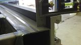
    I have been welding with my new Miller Dynasty 200 Tig. Please go easy on the weld quality; this is my first project and I am learning with every tungsten grind ><.

  2. #12
    Helpfull BT forum member Junior wrench of the Forum
    Join Date
    Sep 2012
    Location
    Coarsegold, CA
    Posts
    86
    Quote Originally Posted by ssray View Post
    If that's the first time you've done any welding I'd say it looks pretty good especially taking on TIG the first time. Good work! BTW, I have a Syncrowave 200 ... Nice machines!

    Scott
    Not the first welding, but my first project with the tig. I have welded for years, O/A, Arc, and Mig. Syncrowaves are great. I almost got a 200 or 250, but decided to go inverter at the last moment.


    Thanks Matt... I will get that transfer punch ordered and get back rolling with this project. I'm kinda disappointed that the drill jig isnt included in the kit anymore, the other builders seemed to be very happy with it.

  3. #13
    Thank you from BT ULTIMUS MAXIMUS STATUS jeepsr4ever's Avatar
    Join Date
    Dec 2002
    Location
    Minnesota
    Posts
    10,042
    Yes half were happy and half had big problems with the jig spinning in the hole then them breaking their drills in the hole on their tables (not good)
    [COLOR=#000000]
    Featuring www.StarLabCNC.com[/URL] for CNC plasma machines
    1-651-433-3689 TOLL FREE 1-855-433-3689

  4. #14
    Helpfull BT forum member Junior wrench of the Forum
    Join Date
    Sep 2012
    Location
    Coarsegold, CA
    Posts
    86
    Quote Originally Posted by jeepsr4ever View Post
    Yes half were happy and half had big problems with the jig spinning in the hole then them breaking their drills in the hole on their tables (not good)
    Our router went dead tonight... so I am on my phone. Hopefully tomorrow I can post a big update with lots of questions and pictures.

  5. #15
    Helpfull BT forum member Junior wrench of the Forum
    Join Date
    Sep 2012
    Location
    Coarsegold, CA
    Posts
    86
    I am still waiting on pics to upload, but a couple questions for now:

    I dont see anywhere in the instructions that mentions installing the motors, the z axis, or the magnetic torch mount. We had to do a lot of spying on YouTube to figure out the orientation of parts and approximately how to hook things up.

    Matt, would you mind if I posted my own version of a comprehensive instruction manual? I think assembling a gantry kit should not be this difficult.

  6. #16
    Thank you from BT ULTIMUS MAXIMUS STATUS jeepsr4ever's Avatar
    Join Date
    Dec 2002
    Location
    Minnesota
    Posts
    10,042
    You can absolutely post up. Just a couple quick things we do before items ship and also some info

    1. The magnetic plate is set to your Z axis and does not need anything special to setup. The unimount torch mount allows the use of .9-1.5" diameter torches. A 5/16-18 bolt holds in the smaller diameter.
    2. The motor mounts are attached one way and there is a left and right. You will note the slot configuration. Attaching the motors can be a little tricky because one side uses a square nut and a slot for retention and the other side uses a flange nut. There are 2 different length socket head capscrews and they are assembled on the reduction units. When you buy a gantry kit the motors are usually not attached to the reduction units and require you to take loose the socket head capscrews and attach the motors. Taking it all apart can make assembly a little tougher.
    3. We used to install the Z axis motor however we found that the assembly is very long to ship.
    [COLOR=#000000]
    Featuring www.StarLabCNC.com[/URL] for CNC plasma machines
    1-651-433-3689 TOLL FREE 1-855-433-3689

  7. #17
    Helpfull BT forum member Junior wrench of the Forum
    Join Date
    Sep 2012
    Location
    Coarsegold, CA
    Posts
    86
    OK, so I had a day off yesterday and got quite a bit done on the table. I ran around Fresno getting tap and transfer punch on wednesday night. It's always interesting running around an industrial area getting things bought right at 5 pm ><.

    First, I unpacked my side rails and their hardware (in a ziploc baggy)...
    I found 38 5/16-18 Allen Screws (18 per rail and 2 extra?), 1 metric? Allen screw (it wasnt 5/16-18 ), and 1 bushing. I later determined this "bushing" to be the drill guide, which was a great help. I didnt even use the transfer punch.

    If people in the future would like to make their own drill guide, the dimensions are 17/64 inside diameter, .5440 outside diameter, and .9490 long. I would recommend making that at least 2 inches long though. It was pretty hard to hold with 2 fingers as I was drilling the holes. My drill has a built in level which helped me a lot with binding against the guide.


    The allen screws for the rails took a 1/4" hex bit to drive them.


    I used a 17/64 drill and a 5/16-18 tapered tap. My 1/4" cordless impact drive did a great job of tapping without blisters. I just had to go SLOW. I didnt break a single tap (I bought 3 just in case), but I could see how it would be easy to do so. I also had a shop vac nearby to suck up all the chips from drilling and tapping as I went.

  8. #18
    Helpfull BT forum member Junior wrench of the Forum
    Join Date
    Sep 2012
    Location
    Coarsegold, CA
    Posts
    86
    Since I had my 2 year old daughter as my only helper… I had to get creative with mounting the rails to the table sides. First, I leveled the table and used the adjustable feet to get it as close as possible. My new 6 and 8 foot levels helped tremendously.


    Then I browsed the internet to see where on the 111” side the 110” rail should be mounted. From my research, I concluded that it should be flush with the cantilevered end of the table. I hope that was right, if not, they can be moved… just a lot of drilling and tapping.

    To mount the rails, I measured to the 8th hole from one side (approximate middle of the rail). It was 58.125”. I transferred that measurement onto the table side. Then I measured the overall width of the rails at ~3.5” with the mounting holes at ~1.75”. I wanted between 5/8 and 7/8 stick up over the table side, so I just measured down 1” on the table side and used a center punch; this would give me ~3/4” stick up of the rail above the table frame.


    This would be my first drilled and tapped hole. I lifted one side of the rail and got it mounted with the one “middle” screw.


    Then I put the 8 foot level on the rail and brought the high end of the rail down to a position that was level so I could clamp it with the vise grips.


    I then proceeded to drill and tap holes in the table frame, using the drill guide, from the center out on the rail; constantly checking for level.


    Now, onto the second rail: This rail needs to be parallel, level, and square with the first rail. Knowing that my table frame was at very least, square, I just measured 58.125” from the end (which would correspond with the 8th hole in the rail, just like before). For the depth measurement, I used the 6 foot level from the other rail across the table. I shimmed it until it was level. Then I measured 1.75” down from the level. That intersection would be my first drilled and tapped hole for the second rail. I followed the same process on the second rail as I did on the first; constantly checking for level both directions. [/URL]

    I found this method to be much easier to handle with just one person than what was mentioned in the instructions. I don’t know if it was the correct way to do it, but I did manage to make everything level, parallel, and square. Using my 8 foot level, I noticed that the table frame had a crown in it. [URL=http://s264.photobucket.com/albums/ii175/slprlx/CNC%20Table/?action=view&current=photobucket-53694-1353080410266.jpg]

    It would be a good idea for anyone welding up the frame on their table to keep checking this as they welded it up. I didn’t have the level at the time I was welding. In response, I think I will shim the water pan to keep it close to the level of the rails (which I know is correct), but I have complete faith that the avhc of the z axis will keep everything in line.
    OK… major hurdle of the rails COMPLETE!

  9. #19
    Helpfull BT forum member Junior wrench of the Forum
    Join Date
    Sep 2012
    Location
    Coarsegold, CA
    Posts
    86
    Now, we needed to put the side plates on. My devoted wife was here to help me from this point forward.
    My side plates had the roller bearings already installed and “preloaded”. However, I did not realize they didn’t have the wipers on them until after I had installed them on the rails.
    First… importantly… wipe down the inside of the rails and get them as clean as possible. I imagine that any dirt between the rollers and the rail would be a bad thing; not to mention a stray metal shaving from the drilling and tapping! Next, remove the black allen screw that will keep you from putting the side plates on. I think, going off memory, these were 5/32 allen.


    Anyways… I don’t know what size man you need to be to “bump them on with the palm of your hand”, but I am not that guy! I got them up to the 3rd wheel and bumped them, hit them with a rubber hammer, and then finally kicked them on squarely with my boot. The last option got them onto the rails and rolling.

    At this point, I installed the wipers onto the side plates. I believe these little screws took a 3/32 allen, but I will double check that. I just tipped the wipers into the rail and then installed them squarely to the side plates. 2 on each side plate. Using this method, you don’t have to worry about damaging the wipers by tearing them on the end of the rail.


    OK… side plates ON! Oh wait… did we install them correctly?
    At this point we scoured YouTube again; trying to find a video that was panned out enough to see the gantry orientation. Bulltear’s forum was down, so I couldn’t look there. I finally remembered that Matt had posted a pretty good overall shot of a 4x8 table on his sale ad on Pirate4x4. Of course, the side plates were on backwards compared to this stock photo…. Repeat all of the above ><
    OK… side plates ON! (again)

  10. #20
    Helpfull BT forum member Junior wrench of the Forum
    Join Date
    Sep 2012
    Location
    Coarsegold, CA
    Posts
    86
    Onto the gantry install! We reviewed the stock photo and YouTube again to determine which side the torch goes onto the gantry. Also to determine which way the rack teeth were oriented.


    The instructions tell to install the 45 degree gussets onto the side plates. I don’t know that this is the best way to approach this. It is VERY IMPORTANT to NOT tighten anything on the gantry until everything is finger tight. Trust me, we spent more time unscrewing bolts to line up new pieces than I care to mention.


    After putting this damn gantry together more times than I can count…. I would suggest flipping the gantry over on the bench and installing all the nutsert plates into the channel, since they probably fell out during shipping like mine. If you don’t do this first… you are gonna be pissed that you have to take the gantry back off again to install the nutserts for the cable carrier brackets. The carrier bracket takes 3 sets of the nutserts and the 45 degree gussets take 4 sets. You should slide 7 nutserts into each channel in the bottom of the gantry.


    The additional 8 nutserts will be used for the side plate reinforcement brackets.

    Once you have the nutserts into the gantry, install the 45 degree gussets, loosely. These need to be able to move enough to line up the 4 bolts to the side plates. THEN lift the gantry up to the side plates and install the 1.75” long 5/16 bolts with nylocs, 4 on each side plate.


    I didn’t do it this way; I wish I had. It seems much more soothing and calming than the 3 steps back to 1 step forward approach that I took.

Posting Permissions

  • You may not post new threads
  • You may not post replies
  • You may not post attachments
  • You may not edit your posts
  •  
Bulltear Ad