Warning: preg_replace(): The /e modifier is deprecated, use preg_replace_callback instead in ..../includes/class_bbcode.php on line 2968 CNC Routing metal on your BullTear/Star Labs Table
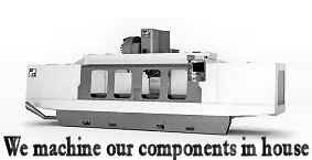
CNC Routing metal on your BullTear/Star Labs Table
Has any of you tried to cut aluminum or steel with your table and the router?
I know its not a Mill by any means but im trying to find out if i would be asking too much of the table to machine out some small billet aluminum parts or light steel cutting.
The Star-Lab machines will out route anything in its class. The reason for this is competitors are using V wheels with 1/4" bolts and bearings on cold rolled steel. The V wheels are always tensioned by a cam bushing. The cam bushing is what gives the slide its preload. It also handle very little side forces on the 1/4" shank bolt before the V wheel either comes loose or starts to ruin the V rail surface. 1/4" bolts are the most common size used the bearings associated with that size are also only rated for so much torque and can and will fail under tension. We used to build with V rail, build with ball bearings on flat cold rolled steel. They are compromise ways of getting cheap motion and look good in pictures. The reason it is important to note issues with a roller bearing is that a standard bearing uses a hardened outer race that cannot take single point pressure without splitting. Its the reason you see people complaining about sub par engineering in the form of bearings splitting in half. Bearings on cold rolled steel makes cheap unreliable motion. It is being sold to unknowing customers daily and replacing the bearings constantly is not something you want to have to do.
We went a different route offering TRUE profile hardened linear rail. On our smallest machine there are 52 individual socket head cap screw bolts holding on the rails and on the largest machine we offer there are over 100 individual socket head cap screw bolts holding the rail in place. If you look at true profile linear rail you see it bolted from the front often with little plastic buttons over the bolt holes. This is a easy way for builders to fasten the rail however your bearings on those rails don't last nearly as long as if the rail is bolted from the back side and is absolutely smooth on the front where the grid, dust and spatter will hit. It is not easy to integrate rails like that witht he bolts on the backside and the front smooth without indents capturing dust and contaminates and it takes knowledge of complex manufacturing processes to get it right. This is something we did with the Star Labs, its something Haas does with their routers and its something that any process machine should have.
It doesn't mean the machine is a CNC mill. It does mean the machine will take up to a 3.5HP router. So if you have 3.5HP you can divide that into material removal of any material. Taking into account the over 4500in oz of torque available means you can do some light steel routing and some light aluminum routing and some medium wood routing. You will be able to have a lot of success using 3/8 and smaller endmills and zero success trying to use a 3/4 endmill. All the systems under $30K that allow routing also use stepper motors unless ordered differently. Stepper motors have a torque curve that falls off to nowhere lands the higher the RPM. Why this is important to understand is with aluminum and steel you may be using a single flute cutting edge tool. So if your at the low end of the router speed your at 8000rpm (up to 20,000rpm on budget motor integrated routers). With a 3/8 endmill your cutting at 785sf which would require 16ipm travel to take off the minimum of .002" on the single tooth endmill on aluminum or it would not remove the aluminum and it would gall and snap the tool. But at 20,000RPM you would be traveling 40ipm. These are the bare minimums for steel and aluminum. For wood you should be in the .020 range so 8000RPM equals 160ipm. But at 20,000RPM your headed for issues because you would be at 400ipm federate. When you get too far under .020 in wood you end up making a hell of a lot of dust.
So if your going to go down the road of routing look to the routers that aren't much over 10,000rpm and special single flute tools. You can experiment with different types of standard steel cutting endmills but the endmill flute depth doesn't eject the chips like it should at high RPMS.
Last edited by jeepsr4ever; 11-09-2014 at 11:11 AM.
And sorry for the long winded answer. It will do some...not any heavy cuts in steel or aluminum. You may be better served looking at a cheap or used CNC mill.
Ive been trying to do a bit of routing on my starlab table and im having issues because of the floating head setup, how do you recommend physically setting up the router/spindle in regards to the z-axis?
Thats exactly what i did but now after running the machine for a bit and admittedly getting a little rough with it the entire z axis slide seems to 'shudder' at the extremities as if its out of alignment or something? I thought maybe because they are just small screws that they might budge a little bit causing it to bind up but it still seems to shudder after loosening them again? just at a bit of a loss thats all i figuered maybe there was another z axis package that could be purchased?
Even a $1 million dollar CNC mill cannot withstand too many if not ONE crash. You may need to call in for some tech help on working through any problems with your Z axis. Out of alignment is most likely exactly what it is. A super strong lateral force may do it.
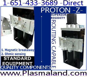
Im well aware of the capabilities of a high end cnc mill vs a starlab table and to be honest im pretty impressed with this thing it certainly has some balls. I dont think the z axis is damaged in any way and even if i were to crash it, judging by its construction i rekon it can take a beating (assuming no X/Y movement just plunging the Z). Is the ballscrew made from SS? Im going to go have a closer look at it now ad setup the spindle again so ill let you know on what i find.. I take it you dont manufacture a z axis designed specificlly for routing then?
There has been some prototyping of a new specific routing Z axis. One thing we like to do is allow users of existing kits the ability to marry these components together. So when it comes out you will be able to bolt the components to the existing Z axis backpanel. The screw is hardened, ground and polished stainless steel.
Has there been any further progress on the new z axis?
Ive been doing heaps of milling AL on my table and i am getting great results but i do run into problems from time to time with the floating axis setup... I should post some pics/videos of some parts that ive made so far, its suprising just how much can be done on something that is mainly a 'plasma' table... Im not sure where your at with the new design but if you need somebody to do some serious milling to test something out let me know!
Heres a couple photos anyways, hopefully they work:
One is of a motor mount i made to fit a small bosch router to the machine for a backup, i milled it from a 40mm thick piece of ally billet with a $5 half inch router bit - suprisingley it turned really nice! The other is of 2 small plates i drilled out for a prototype reactor of some sort, they are 6mm thick 253MA stainless steel (very hard stuff) with a 4mm dia. hole 3mm deep then a 1mm hole all the way through! I havent counted but i think there is 500 - 600 holes total in those 2 small plates (holes are only spaced 8mm apart) and man they turned out awsome! All on the starlab table too!


 Reply With Quote